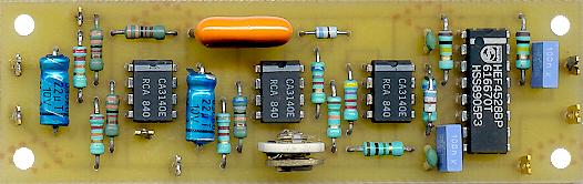
Now let's see how popular the PCB. Here comes into play a very useful tool to consider,
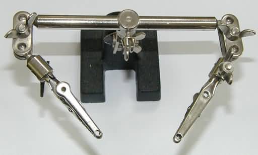 is called "Third Hand" (third hand). It is very comfortable working with her. What I do is put the board between the two alligator clips to the side of the tracks looking up, so to insert the components you have to turn all the tools, so that later when you have to weld the tool is in its normal position. After welding, just missing trim excess duckling "with pliers.
 welding technique is simple, first plug the welder, and you wait a few minutes until hot. Then feeds the tool tip with a little Estani as to coat once. After quickly heat the place where you will go the weld (in our case the union of the component leg and the track) and then with the other hand you "feed" the welder Estani. It is a matter of practice until you take your hand. TENE WELDER CARE BECAUSE YOU ARE A VERY HIGH TEMPERATURE. Every now and will happen to you that the solder does not "get."
 What you have to do is try a little more, but Estani clean the soldering tip with a damp sponge or rub against something metal welder for the Estani go. For the sponge you can use the media to bring welders. is recommended that you have a support for the welder to support when you're not using.
 The provisional
welding is as follows:
-network socket of Integrated Circuits and trimpots
-resistors, capacitors
-Diodos/Transistores
-network socket of Integrated Circuits and trimpots: These components do not have too much science.
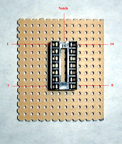 Regarding you have to grope network socket on the board until the pins will accommodate the holes. Then weld leg by leg, being careful not to touch the welds. I recommend you solder the legs from top to bottom. The pins are counted as in the photo. Oh, and do not forget to put the integrated network socket when you finish, but the pedal Funk P!
 trimpots As there are several formats. Recall that a trimpot is a potentiometer, but for the board. These are used in the plate, as it is only necessary to adjust them once. They come in a turn and multiturn, the first using only a lap to cover the resistance range, instead, used several times multiturn allow greater precision. There are also vertical and horizontal
 . Usually we use a back and vertical, as they are more comfortable. Generally the layout already prepared for the disposition of the legs of the trimpot, so you'll have to grope. It can happen to you when you turn the plate welding, the component will fall. In this case when you put a little bend your legs so that when you give back the plate the component does not fall.
 -Resistance:
 resistors generally are used for the purposes of Carbon and 1 / 4 Watt. The metal is also Film, and is said to have better quality, but are more expensive, and the difference is rarely noticeable.
 Poné all resistance and then SOLDAL. The resistors are not damaged by excessive heat, so you would not have to worry about overheating.
To identify the strengths you can use either a digital tester to measure resistance in ohms, or you can walk you through the colored bands.

-Capacitors: capacitors to use are: ceramic pF values, polyester film for kids values, and electrolyte for the values \u200b\u200bfrom 1uF. There are also ceramic kids values, but for audio circuits are used in polyester film, so make sure that all capacitors give you are of polyester.

-Ceramic

-FIML
Polyester

-Electrolyte
-Diodes: The diodes are very small . These components are sensitive to heat. Try not to overheat. Forgotten If you tenes that diode in hand with a magnifying glass you can see the description printed on the body.

-Transistors: components are more difficult to weld. Overall All are easy, but this has a bit more difficult. The problems that arise are: on the one hand they are very sensitive to heat, so you have to be careful, and the other has three legs that stick out and can inadvertently "connect" their joints in the PCB.


 Finally


 -www.diystompboxes.com


